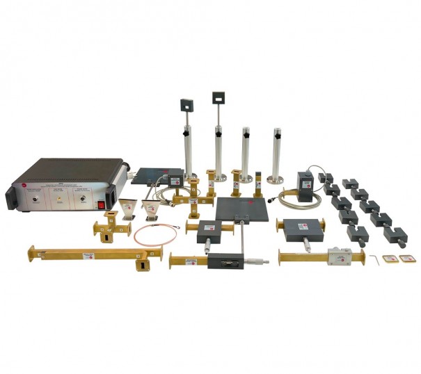
The Computer Controlled Microwave Unit, “EMIC”, integrates a microwaves measuring test bench formed by microwaves generator, a kit of different standardized (WR-90) waveguides devices (horns antennas, attenuators, etc), measure devices (power meter, slotted line, etc), a control interface box to connect to the computer and a software for data acquisition and parameters calculation.
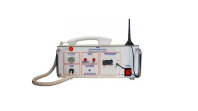
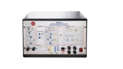
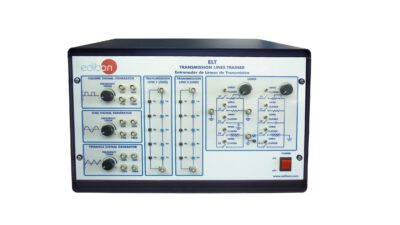
This Computer Controlled Unit is supplied with the EDIBON Computer Control System (SCADA), and includes: The unit itself + a Control Interface Box+ Computer Control, Data Acquisition and Data Management Software Packages, for controlling the process and all parameters involved in the process.
SPECIFICATION
Power meter:
- Based on thermistor. Wide frequency range: 10 – 12000 MHz.
- Typically level range: -55 dBm – +18 dBm. Stability over temperature.
- Slope: -25 mV/dB.
- Connector to interface box.
Slotted line:
- Tunnel diode detector mounted.
- Frequency range: 2 – 18 GHz. VSWR max: 3.5:1.
- Maximum input power: 100 mW (20 dBm). Work in the quadratic detection zone.
- Designed for 8.2 – 12.4 GHz (X-band). Longitudinal movable diode detector holder.
- Millimeter ruler. Waveguide in the standard size WR-90.
- SMA connector to Interface box.
Gunn oscillator (microwave signal generator):
- Gunn oscillator diode. Frequency band: X band (fixed at 10.525 GHz).
- Power output: 10 dBm. Waveguide in the standard size WR-90.
- Connector to interface box.
Broad-wall waveguide directional coupler:
- Designed for 8.2 – 12.4 GHz (X-band). Three ports (input, output and coupled).
- Waveguide in the standard size WR-90.
Cross-guide waveguide directional coupler:
- Designed for 8.2 – 12.4 GHz (X-band). Four ports (input, output, isolated and coupled). Waveguide in the standard size WR-90.
Hybrid Tee:
- Designed for 8.2 – 12.4 GHz (X-band)
- Vertical variable attenuator:
- Designed for 8.2 – 12.4 GHz (X-band). Precision micrometer. Waveguide in the standard size WR-90.
Horizontal variable attenuator:
- Designed for 8.2 – 12.4 GHz (X-band). Precision micrometer. Waveguide in the standard size WR-90.
Termination load (Dummy load):
- Designed for 8.2 – 12.4 GHz (X-band). Adapted load. Waveguide in the standard size WR-90.
Two short circuit terminations.
Two horn antennas:
- Designed for 8.2 – 12.4 GHz (X-band). Sectorial horn flared in the direction of the electric plane (H-plane). Waveguide in the standard size WR-90.
Adjustable termination:
- Designed for 8.2 – 12.4 GHz (X-band). Movable short circuit. Precision micrometer. Waveguide in the standard size WR-90.

