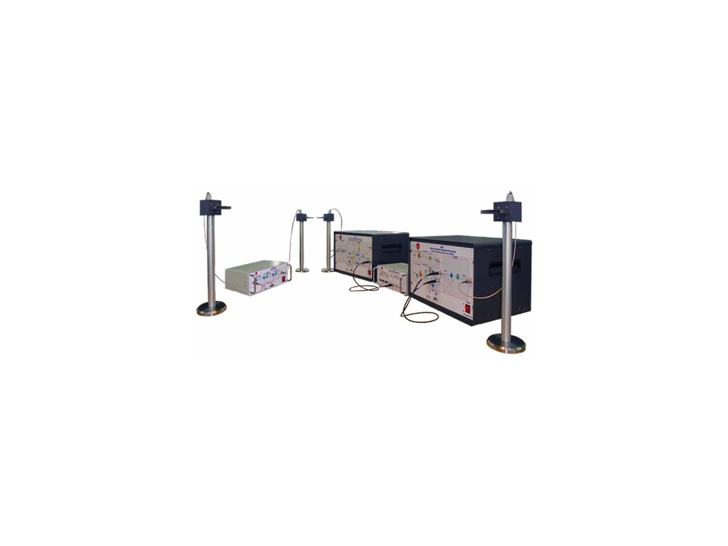
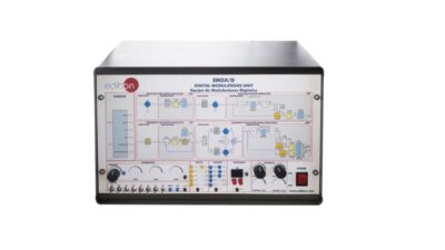
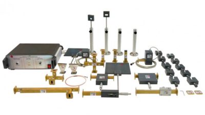
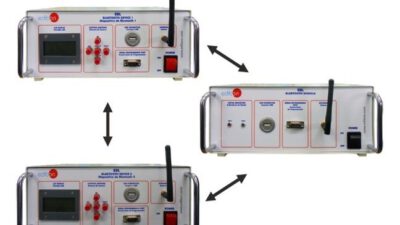
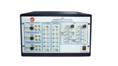
The “ESA” trainer is an advanced system that operates in conjunction with a computer (PC), which allows students an easy way to manage and visualize the data. The “ESA” software allows to perform multiple actions: configuring the sending data, selecting the desired test point to visualize, selecting different faults in the equipment, etc.
The “ESA” trainer is divided into different modules to allow the student a better understanding of the unit. These modules are: Satellite Ground Transmitter Station, Satellite Ground Receiver Station, Satellite Repeater and the Control Signal and Data Acquisition Module.
SPECIFICATION
Generators:
- Analog Generator:
- Analog signal parameters configured with the software.
- Audio Frequency Range: 0 Hz to 100 Hz.
- Digital Generator:
- Digital signal parameters configured with the software.
- One byte sent per cycle
Modulators:
- Analog Modulator:
FM modulator based on Voltage Controlled Oscillator.
- Digital Modulator:
- DQPSK modulator based on PSK modulator.
- First Local Oscillator: 10 kHz.
- Second Local Oscillator: 916 MHZ.
- BNC connector to Satellite Ground Transmitter Antenna.
Satellite Repeater (in metallic box):
- Down Converter (Two steps down-converter): Receive the Uplink and recover the original modulated signal:
- First Local Oscillator: 916 MHZ.
- Second Local Oscillator: 10 kHz.
- BNC connector to Satellite Receiver Antenna.
- First Local Oscillator: 8 kHz.
- Second Local Oscillator: 869 MHZ.
- BNC connector to Satellite Transmitter Antenna.
Satellite Ground Receiver Station (in metallic box):
- Down Converter (Two steps down-converter): Receive the Downlink and recover the original modulated signal:
- First Local Oscillator: 869 MHZ.
- Second Local Oscillator: 8 kHz.
- BNC connector to Satellite Ground Receiver Antenna.
Demodulators:
- Analog Demodulator:
FM demodulator based on PLL circuit.
- Digital Demodulator:
DQPSK demodulator based on Costas Loop circuit.

