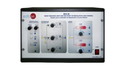
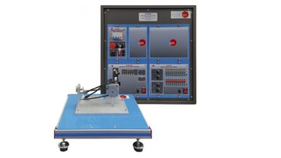
The Computer Controlled Modular Control and Regulation Unit, “RYC/T”, allows the students to simulate an integrator system, a first order system and a second order system and regulate them with a PID controller or Lead and Lag compensator. The unit also allows to simulate perturbations and offsets to analyze the response of the system.
This Computer Controlled Unit is supplied with the EDIBON Computer Control System (SCADA), and includes: The unit itself + a Data Acquisition Board + Computer Control, Data Acquisition and Data Management Software Packages, for controlling the process and all parameters involved in the process.
SPECIFICATION
Metallic box
- Reference signals module
Step output. Square output. Ramp output. Sine output.
Step: amplitude: 0 V to 5 V, frequency: 0Hz to 200 Hz.
Square: amplitude: ±10 V, frequency: 0Hz to 200 Hz.
Ramp: amplitude: ±10 V, frequency: 0Hz to 200 Hz.
Sine: amplitude: ±10 V, frequency: 0Hz to 200 Hz
- PID controller module:
P controller: Kc: -10 to +10.
I controller: Ti: 0 to 100 s.
D controller: Td: 0 to 100 s
Sample time: 0.1 to 100 ms
- Lead/Lag compensator:
K lead: 1 to 100 s.
K lag: 1 to 100 s.
Gain: 1 to 10.
Sample time: 0.1 to 100 ms
- Integrator system:
Gain: -10 to 10.
Saturation: -10 to 10
- First order system:
Gain: 0 to 10. Time constant T: 0 to 100 s.
- Second order system:
Gain: 1 to 10.
Damping coefficient x: 0 to 1.5 in steps of 0.1
Natural frequency (w n): 1Hz to 2 p*100 rad/s (100 Hz)
- Perturbation module
Perturbation value: -10 to 10
- Offset module:
Offset value: -10 to 10
- Analog Inputs: 4 analog inputs.
Connector to computer

